Turn on suggestions
Auto-suggest helps you quickly narrow down your search results by suggesting possible matches as you type.
Showing results for
- Republic of Gamers Forum
- Motherboards
- Intel 700 & 600 Series
- Re: ASUS MAXIMUS Z690 EXTREME & i9-12900K GUIDE - ...
Options
- Subscribe to RSS Feed
- Mark Topic as New
- Mark Topic as Read
- Float this Topic for Current User
- Bookmark
- Subscribe
- Mute
- Printer Friendly Page
ASUS MAXIMUS Z690 EXTREME & i9-12900K GUIDE - Load Lines, VF Curves, Adaptive Voltage
Options
- Mark as New
- Bookmark
- Subscribe
- Mute
- Subscribe to RSS Feed
- Permalink
01-18-2022 12:08 AM - edited 10-20-2023 05:52 PM
Disclaimer !
These settings and methods
are outside Intel's specifications,
just like any other overclocking method.
----------------------------------------------------
These settings and methods
are outside Intel's specifications,
just like any other overclocking method.
----------------------------------------------------
You can find an updated material here
Introduction:
In a world increasingly concerned with natural resources, the watchword is efficiency. So, it's time to look at adaptive voltage and by core with other eyes.
This is not to say that the era of overclocking with "Sync all cores" and "fixed voltage" is over, as it is much easier and faster to do, and brings good results, but it is not "Single Thread" efficient.
It is worth remembering that Intel supplies its processors operating stock in "by core" and "Adaptive Voltage", and now goes beyond, and manufactures its processors with performance cores and efficiency cores.
But anyway, why would I trade the easiest way to overclock it for a more complicated one? The answer is simple, because we like complicated things. Now a day, with the current processing capability, it is not necessary to overclock, and even then we do this complicated thing, just for a few extra frames. So we do it for fun. The overclock itself can be fun like a game. After all, isn't it nice to know that we can go a little over the limit with that hardware we bought?
Thanks:
My thanks to Shamino and Asus for all their support and for inviting me to join the ROG Maximus Z690 platform test team.
My sincere thanks to Falkentyne and Cstkl1 for their help during testing.
You can find an updated material here
I
7,632 Views
9 REPLIES 9
Options
- Mark as New
- Bookmark
- Subscribe
- Mute
- Subscribe to RSS Feed
- Permalink
01-18-2022 12:15 AM
Understanding LLC, AC_LL & DC_LL:
Let's first understand load lines:
For this, didactically, we will exchange the electric current for a flow of water.

Our goal is to adjust the circuit so that the tanks remain at the same levels at all times, regardless of LOAD.
The resistance to the passage of water in the “Load Line� piping is physical and intrinsic to its construction.
(This is the physical wire from the VRM to the CPU).
As the LOAD varies all the time, the CPU tank level tends to get higher or lower than the VRM tank in an uncontrolled way.
So let's take control !
For that we have 2 pumps: the LLC pump and the AC_LL pump.
The first thing to do is to choose an LLC pump that will compensate for losses in the load line pipe.
(This is the VRM impedance characteristic, which determines the voltage drop as current flows).
Ideally, the pump should be neither too strong nor too weak.
We have 8 LLC pumps to choose from.
Pumps #7 and #8 are very strong and are not viable for daily use. So we have six pumps left.
It seems to me a good idea to choose an intermediate pump, #3 for example, but we can choose any one of these 6 pumps, as long as we make adjustments in the control circuit.
All this control will be done by the CPU, so we must inform which pump we choose through the DC_LL parameter. This way, the value of DC_LL (milliohms) must match the value of LLC (milliohms) chosen so that the CPU does all the calculations correctly.
The next pump to choose is AC_LL.
(This is the load variation compensation component).
This parameter makes the CPU, upon perceiving an increase in the water flow to the LOAD, to increase the VID value sent to the VRM, in order to anticipate the losses that this flow increase could cause. Therefore, the VRM uses the LLC and AC_LL pumps to fulfill the CPU VID request.
So if we have a stronger LLC pump, we can use a weaker AC_LL pump and vice versa.
Some combinations are not recommended, for example: two weak pumps or two strong pumps.
All this game can be done according to the desired goals.
Comparison with fixed voltage:

When we decide to use "voltage override" we turn off all this controls described before.
The selected LLC pump and the VID manually set will feed the level of the CPU tank without a control.
In this case, when the flow to the load rises, the level of the CPU tank goes down... And when the flow to the load decreases, the level of the CPU tank goes up...
So, bye bye level control.... 😂
You will need to run all the time with more voltage than you need, for that specific frequency, just waiting for when the heavy load comes.
If you think you can do a better job than the CPU algorithm, use fixed voltage, don't worry about AC_LL and DC_LL. Set an LLC #5, 6 or 7...
But I think it's a better idea to use this extra voltage to reach high frequencies...
Choosing LLC, AC_LL and DC_LL:
The first step in planning overclocking is to set the full load frequency.
But for everything to work well, and as expected, we must first set up the LLC, AC_LL and DC_LL.
If the chosen Full Load frequency has a unique VF point for this frequency, we will be more free to choose LLC, DC_LL and AC_LL.
Otherwise, if the Full Load frequency does not have a unique VF point, we will have to choose the best Load Line set that allows us, through interpolation of the points, to set the voltage referring to the frequency chosen for Full Load.
The basic rule of adaptive voltage and TVB overclock (OCTVB) is to work with vdroop to your advantage.
This way, using a less aggressive LLCs will give you greater leeway for high frequencies.
In a simplified way, load line should influence overclocking as follows:
Low loads, low Vdroop, high voltages, high frequencies.
High loads, high Vdroop, low voltages, low frequencies.
You can configure the TVB overclock using any LLC, it all depends on your processor and what you want to do with it.
This Is the Board Maximus Z-690 Extreme LLC Impedance:
LLC1: 1.75 milliohms
LLC2: 1.46 milliohms
LLC3: 1.1 milliohms
LLC4: 0.98 milliohms
LLC5: 0.73 milliohms
LLC6: 0.49 milliohms
LLC7: 0.24 milliohms
LLC8: 0.01 milliohms (flat).
The impedance values of the DC_LL shall be used according to the LLC chosen, so that the CPU performs its internal voltage and power calculations accurately.
Impedance stake:
DC_LL=LLC: The CPU performs correct VID and power calculations;
DC_LL< the="" cpu="" performs="" higher="" than="" real="" vid="" and="" power="" calculations="">DC_LL>LLC: The CPU performs lower than real VID and power calculations.
So, rule is: ALWAYS TUNE The DC_LL according to the LLC chosen.
Below are some configuration suggestions for the 12900K:
LLC#1
DC_LL = 1.75
AC_LL = 0.60
LLC#2
DC_LL = 1.46
AC_LL = 0.46
LLC#3
DC_LL 1.1
AC_LL 0.25
LLC#4
DC_LL 0.98
AC_LL 0.20
Undestanding the LLC, DC_LL and AC_LL numbers:
LLC controls the output impedance of our VRM, and MB vendors allow us to change and control this impedance.
DC_LL is the parameter that informs the CPU the VRM impedance.
If you decide to use LLC #1, the impedance is 1.75mohm, then you need to inform the CPU of this impedance using the DC_LL parameter.
If you use LLC #4 then the DC_LL should be 0.98.
To find the LLC impedance, you need to test one by one LLC and change the DC_LL until the VRM power matches the CPU power and the VID matches the Vcore. Once they match, you found LLC impedance.
AC_LL is a parameter that compensates for voltage loss due to your load line impedance, and you need to guess and test a different number for each LLC.
If you use a high impedance LLC you will need a higher AC_LL, on the other hand if you use a low impedance LLC you will need a low AC_LL
Note that on Asus MB, LLC # high means low impedance. And LLC # low means high impedance.
So never use a low impedance LLC with a high AC_LL... This will result in a very high voltage....
That's why I recommend an IA VR voltage limit of 1500mv....
So if you commit an error, the voltage will have a limit of 1.50v.
Simplifying the formulas:
You have the VF curve VID... Let's call it raw-vid.
That VID you see in hw-info, let's call it VID
You have the LLC impedance, let's call it LLC#
You have the DC_LL impedance parameter, let's call it DC_LL
You have AC_LL impedance compensation, let's call it AC_LL.
You have the CPU current, let's call it Amp.
You have the offsets and temperature components that we're not going to use to make things easier right now.
You have the Vcore, and let's call it Vcore.
So....
VID = raw-vid + (AC_LL * Amp) - (DC_LL * Amp)
Vcore = raw-vid + (AC_LL * Amp) - (LLC# * Amp)
This is how I found the LLC impedance.
If DC_LL = LLC than VID=Vcore at full load.
The Intel recommendation is to use AC_LL = DC_LL and LLC#3 (for asus MB)
So the intel recommendation is:
LLC = 1.1 mhom
AC_LL = 1.1mhom
DC_LL = 1.1mhom
It's a very conservative setting that will work with any poor MB.
Using AC_LL = LLC #, the lost voltage caused by VRM impedance will be compensated by AC_LL.
But we want to UNDERVOLT the CPU, right?
So, we will use AC_LL < DC_LL
But how to find the correct numbers?
Testing the combinations.
Each CPU will respond depending on the silicon lottery.
I've made suggestions here, so you'll need to understand all of this and make some corrections.
The LLC effect:
Many like to tinker with their motherboard load-line settings to achieve better overclocking results. But how does this setting really work and how does the voltage output change with it? Check below to find out.
What is Load-Line?
The load-line setting, normally in mΩ (milliohms), determines how much the output voltage decreases when loaded. This is derived from Ohm’s Law U = R*I. The drop in output voltage is calculated as load-line * Iout (output current). For example a load-line of 1 mΩ and output current of 100 A, dU = 0.001 Ω * 100 A = 0.100 V. At 1.300 V set-point output voltage, when loaded with 100 A the output would really be 1.300 – 0.100 = 1.200 V. The primary reason for using a load-line in modern systems is to reduce voltage spikes (overshoot) when going from high to low output current and achieve a more predictable behavior.
Load-Line Levels or similar are profiles created by motherboard manufacturers to obfuscate and “simplify� different load-line values for users. Another reason for these profiles is because additional VRM (Voltage Regulator Module) settings may need to adjusted along with the load-line value to keep it operating within spec.
The captures below show the output voltage transient behavior when loaded with about 70 A for ~150 μs. The LLC1 capture illustrates ideal load-line behavior.
As the load-line value decreases (higher level), the line flattens and the under/overshoot spikes at start and finish become more pronounced.
The lowest voltage point at the beginning of the load transient does not improve much. In this case, using a Load-Line Level of above 3 seems questionable.
The load voltage would increase meaning higher power consumption, but the worst case lowest voltage would stay the same.


Credits: ElmorLabs
Setting the Full Load frequency:
P-51x/E-40x is a Full Load frequency that almost all 12900k processors can support, even with an AIO type cooling solution, so we'll follow with this example.
(If your CPU does not support this configuration due to high temperatures, you can try the P-50x / E-39x.)
Now we must find out what the minimum voltage for the full load frequency, in a way to optimize the working temperature of the CPU and the dissipated power.
To find the minimum voltage for Full Load we need to synchronize all performance cores at 51x and all efficiency cores at 40x.
The traditional way is to set load lines (e.g. LLC#4, AC_LL=0.20, DC_LL= 0.98), select "Sync All P-Cores" to 51x and "Sync all E-Cores" to 40x, set a value to "Fixed Voltage" and then find the minimum Vcore voltage that maintains system stability.
This is a good way to get started, as we'll already know the minimum Vcore in advance to maintain stability at full load P-51x/E-40x.
But let's do something different to get us started using “By Core�.
Instead of selecting "Sync All Cores", let's select "By core usage" and set all P-cores to 51x and all E-cores to 40x

This way all cores will be synchronized and full load will be P-51X/E-40x.
Defining Load Lines:
Now we must choose which LLC we will use for our OCTVB.
(If you used LLC#4, AC_LL=0.20, DC_LL= 0.98 to find the minimum voltage for Full Load by synchronizing the cores, now it's time to go back to LLC#1 to use Vdroop to our advantage for high frequencies.)
Let's start by testing LLC#1:

Now let's tune AC_LL and DC_LL to LLC#1
AC_LL= 0.60
DC_LL= 1.75

And set the "IA VR Voltage Limit" to 1500mv.
This configuration will avoid any voltage higher than 1.50V with the penalty of some high frequencies.
*** The Value of 1500mv is a pesonal choice. You can try 1550, 1600 or 1700.
''''''''''''''''''''''''''''''''''''''''''''''''''''''''''''''''''''''''''''''''''''''''''''''''''''''''''''''''''''''''''''''''''''''''''''''''''''''''
IA VR Voltage Limit
Asus included in the BIOS of its Z-690 MBs the control "IA VR Voltage Limit".
This control limits the VCore voltage to the selected value, preventing the CPU from reaching frequencies that require higher voltages than the selected one.
In practice this control limits the maximum CPU frequency based on the voltage limit of the established VCore.
The default value (AUTO) is 2500mv, that is, by default there is no frequency limitation due to Vcore voltage.
This control will be very useful for limiting the highest frequencies while maintaining system stability.
As a suggestion, the initial value of 1500mv is quite reasonable.
''''''''''''''''''''''''''''''''''''''''''''''''''''''''''''''''''''''''''''''''''''''''''''''''''''''''''''''''''''''''''''''''''''''''''''''''''''''''
Let's first understand load lines:
For this, didactically, we will exchange the electric current for a flow of water.
Our goal is to adjust the circuit so that the tanks remain at the same levels at all times, regardless of LOAD.
The resistance to the passage of water in the “Load Line� piping is physical and intrinsic to its construction.
(This is the physical wire from the VRM to the CPU).
As the LOAD varies all the time, the CPU tank level tends to get higher or lower than the VRM tank in an uncontrolled way.
So let's take control !
For that we have 2 pumps: the LLC pump and the AC_LL pump.
The first thing to do is to choose an LLC pump that will compensate for losses in the load line pipe.
(This is the VRM impedance characteristic, which determines the voltage drop as current flows).
Ideally, the pump should be neither too strong nor too weak.
We have 8 LLC pumps to choose from.
Pumps #7 and #8 are very strong and are not viable for daily use. So we have six pumps left.
It seems to me a good idea to choose an intermediate pump, #3 for example, but we can choose any one of these 6 pumps, as long as we make adjustments in the control circuit.
All this control will be done by the CPU, so we must inform which pump we choose through the DC_LL parameter. This way, the value of DC_LL (milliohms) must match the value of LLC (milliohms) chosen so that the CPU does all the calculations correctly.
The next pump to choose is AC_LL.
(This is the load variation compensation component).
This parameter makes the CPU, upon perceiving an increase in the water flow to the LOAD, to increase the VID value sent to the VRM, in order to anticipate the losses that this flow increase could cause. Therefore, the VRM uses the LLC and AC_LL pumps to fulfill the CPU VID request.
So if we have a stronger LLC pump, we can use a weaker AC_LL pump and vice versa.
Some combinations are not recommended, for example: two weak pumps or two strong pumps.
All this game can be done according to the desired goals.
Comparison with fixed voltage:
When we decide to use "voltage override" we turn off all this controls described before.
The selected LLC pump and the VID manually set will feed the level of the CPU tank without a control.
In this case, when the flow to the load rises, the level of the CPU tank goes down... And when the flow to the load decreases, the level of the CPU tank goes up...
So, bye bye level control.... 😂
You will need to run all the time with more voltage than you need, for that specific frequency, just waiting for when the heavy load comes.
If you think you can do a better job than the CPU algorithm, use fixed voltage, don't worry about AC_LL and DC_LL. Set an LLC #5, 6 or 7...
But I think it's a better idea to use this extra voltage to reach high frequencies...
Choosing LLC, AC_LL and DC_LL:
The first step in planning overclocking is to set the full load frequency.
But for everything to work well, and as expected, we must first set up the LLC, AC_LL and DC_LL.
If the chosen Full Load frequency has a unique VF point for this frequency, we will be more free to choose LLC, DC_LL and AC_LL.
Otherwise, if the Full Load frequency does not have a unique VF point, we will have to choose the best Load Line set that allows us, through interpolation of the points, to set the voltage referring to the frequency chosen for Full Load.
The basic rule of adaptive voltage and TVB overclock (OCTVB) is to work with vdroop to your advantage.
This way, using a less aggressive LLCs will give you greater leeway for high frequencies.
In a simplified way, load line should influence overclocking as follows:
Low loads, low Vdroop, high voltages, high frequencies.
High loads, high Vdroop, low voltages, low frequencies.
You can configure the TVB overclock using any LLC, it all depends on your processor and what you want to do with it.
This Is the Board Maximus Z-690 Extreme LLC Impedance:
LLC1: 1.75 milliohms
LLC2: 1.46 milliohms
LLC3: 1.1 milliohms
LLC4: 0.98 milliohms
LLC5: 0.73 milliohms
LLC6: 0.49 milliohms
LLC7: 0.24 milliohms
LLC8: 0.01 milliohms (flat).
The impedance values of the DC_LL shall be used according to the LLC chosen, so that the CPU performs its internal voltage and power calculations accurately.
Impedance stake:
DC_LL=LLC: The CPU performs correct VID and power calculations;
DC_LL< the="" cpu="" performs="" higher="" than="" real="" vid="" and="" power="" calculations="">DC_LL>LLC: The CPU performs lower than real VID and power calculations.
So, rule is: ALWAYS TUNE The DC_LL according to the LLC chosen.
Below are some configuration suggestions for the 12900K:
LLC#1
DC_LL = 1.75
AC_LL = 0.60
LLC#2
DC_LL = 1.46
AC_LL = 0.46
LLC#3
DC_LL 1.1
AC_LL 0.25
LLC#4
DC_LL 0.98
AC_LL 0.20
Undestanding the LLC, DC_LL and AC_LL numbers:
LLC controls the output impedance of our VRM, and MB vendors allow us to change and control this impedance.
DC_LL is the parameter that informs the CPU the VRM impedance.
If you decide to use LLC #1, the impedance is 1.75mohm, then you need to inform the CPU of this impedance using the DC_LL parameter.
If you use LLC #4 then the DC_LL should be 0.98.
To find the LLC impedance, you need to test one by one LLC and change the DC_LL until the VRM power matches the CPU power and the VID matches the Vcore. Once they match, you found LLC impedance.
AC_LL is a parameter that compensates for voltage loss due to your load line impedance, and you need to guess and test a different number for each LLC.
If you use a high impedance LLC you will need a higher AC_LL, on the other hand if you use a low impedance LLC you will need a low AC_LL
Note that on Asus MB, LLC # high means low impedance. And LLC # low means high impedance.
So never use a low impedance LLC with a high AC_LL... This will result in a very high voltage....
That's why I recommend an IA VR voltage limit of 1500mv....
So if you commit an error, the voltage will have a limit of 1.50v.
Simplifying the formulas:
You have the VF curve VID... Let's call it raw-vid.
That VID you see in hw-info, let's call it VID
You have the LLC impedance, let's call it LLC#
You have the DC_LL impedance parameter, let's call it DC_LL
You have AC_LL impedance compensation, let's call it AC_LL.
You have the CPU current, let's call it Amp.
You have the offsets and temperature components that we're not going to use to make things easier right now.
You have the Vcore, and let's call it Vcore.
So....
VID = raw-vid + (AC_LL * Amp) - (DC_LL * Amp)
Vcore = raw-vid + (AC_LL * Amp) - (LLC# * Amp)
This is how I found the LLC impedance.
If DC_LL = LLC than VID=Vcore at full load.
The Intel recommendation is to use AC_LL = DC_LL and LLC#3 (for asus MB)
So the intel recommendation is:
LLC = 1.1 mhom
AC_LL = 1.1mhom
DC_LL = 1.1mhom
It's a very conservative setting that will work with any poor MB.
Using AC_LL = LLC #, the lost voltage caused by VRM impedance will be compensated by AC_LL.
But we want to UNDERVOLT the CPU, right?
So, we will use AC_LL < DC_LL
But how to find the correct numbers?
Testing the combinations.
Each CPU will respond depending on the silicon lottery.
I've made suggestions here, so you'll need to understand all of this and make some corrections.
The LLC effect:
Many like to tinker with their motherboard load-line settings to achieve better overclocking results. But how does this setting really work and how does the voltage output change with it? Check below to find out.
What is Load-Line?
The load-line setting, normally in mΩ (milliohms), determines how much the output voltage decreases when loaded. This is derived from Ohm’s Law U = R*I. The drop in output voltage is calculated as load-line * Iout (output current). For example a load-line of 1 mΩ and output current of 100 A, dU = 0.001 Ω * 100 A = 0.100 V. At 1.300 V set-point output voltage, when loaded with 100 A the output would really be 1.300 – 0.100 = 1.200 V. The primary reason for using a load-line in modern systems is to reduce voltage spikes (overshoot) when going from high to low output current and achieve a more predictable behavior.
Load-Line Levels or similar are profiles created by motherboard manufacturers to obfuscate and “simplify� different load-line values for users. Another reason for these profiles is because additional VRM (Voltage Regulator Module) settings may need to adjusted along with the load-line value to keep it operating within spec.
The captures below show the output voltage transient behavior when loaded with about 70 A for ~150 μs. The LLC1 capture illustrates ideal load-line behavior.
As the load-line value decreases (higher level), the line flattens and the under/overshoot spikes at start and finish become more pronounced.
The lowest voltage point at the beginning of the load transient does not improve much. In this case, using a Load-Line Level of above 3 seems questionable.
The load voltage would increase meaning higher power consumption, but the worst case lowest voltage would stay the same.
Credits: ElmorLabs
Setting the Full Load frequency:
P-51x/E-40x is a Full Load frequency that almost all 12900k processors can support, even with an AIO type cooling solution, so we'll follow with this example.
(If your CPU does not support this configuration due to high temperatures, you can try the P-50x / E-39x.)
Now we must find out what the minimum voltage for the full load frequency, in a way to optimize the working temperature of the CPU and the dissipated power.
To find the minimum voltage for Full Load we need to synchronize all performance cores at 51x and all efficiency cores at 40x.
The traditional way is to set load lines (e.g. LLC#4, AC_LL=0.20, DC_LL= 0.98), select "Sync All P-Cores" to 51x and "Sync all E-Cores" to 40x, set a value to "Fixed Voltage" and then find the minimum Vcore voltage that maintains system stability.
This is a good way to get started, as we'll already know the minimum Vcore in advance to maintain stability at full load P-51x/E-40x.
But let's do something different to get us started using “By Core�.
Instead of selecting "Sync All Cores", let's select "By core usage" and set all P-cores to 51x and all E-cores to 40x
This way all cores will be synchronized and full load will be P-51X/E-40x.
Defining Load Lines:
Now we must choose which LLC we will use for our OCTVB.
(If you used LLC#4, AC_LL=0.20, DC_LL= 0.98 to find the minimum voltage for Full Load by synchronizing the cores, now it's time to go back to LLC#1 to use Vdroop to our advantage for high frequencies.)
Let's start by testing LLC#1:
Now let's tune AC_LL and DC_LL to LLC#1
AC_LL= 0.60
DC_LL= 1.75
And set the "IA VR Voltage Limit" to 1500mv.
This configuration will avoid any voltage higher than 1.50V with the penalty of some high frequencies.
*** The Value of 1500mv is a pesonal choice. You can try 1550, 1600 or 1700.
''''''''''''''''''''''''''''''''''''''''''''''''''''''''''''''''''''''''''''''''''''''''''''''''''''''''''''''''''''''''''''''''''''''''''''''''''''''''
IA VR Voltage Limit
Asus included in the BIOS of its Z-690 MBs the control "IA VR Voltage Limit".
This control limits the VCore voltage to the selected value, preventing the CPU from reaching frequencies that require higher voltages than the selected one.
In practice this control limits the maximum CPU frequency based on the voltage limit of the established VCore.
The default value (AUTO) is 2500mv, that is, by default there is no frequency limitation due to Vcore voltage.
This control will be very useful for limiting the highest frequencies while maintaining system stability.
As a suggestion, the initial value of 1500mv is quite reasonable.
''''''''''''''''''''''''''''''''''''''''''''''''''''''''''''''''''''''''''''''''''''''''''''''''''''''''''''''''''''''''''''''''''''''''''''''''''''''''
Options
- Mark as New
- Bookmark
- Subscribe
- Mute
- Subscribe to RSS Feed
- Permalink
01-18-2022 12:26 AM
Reserved
Options
- Mark as New
- Bookmark
- Subscribe
- Mute
- Subscribe to RSS Feed
- Permalink
01-18-2022 12:25 AM
System startup:
Boot the system with the following settings:
LLC=#1
AC_LL=0.60
DC_LL=1.75
C-State = Enable
Voltage Optimization = Enable
IA VR voltage Limit=1500 (or the limit you think is good for you)
By core = P-51x8 / E-40x8
Adaptive voltage (AUTO)
''''''''''''''''''''''''''''''''''''''''''''''''''''''''''''''''''''''''''''''''''''''''''''''''''''''''''''''''''''''''''''''''''''''''''''''''''''''''
It's time to test system stability in Full Load.
Run the CB-R23 and check the stability of the system.
''''''''''''''''''''''''''''''''''''''''''''''''''''''''''''''''''''''''''''''''''''''''''''''''''''''''''''''''''''''''''''''''''''''''''''''''''''''''
If the system is not stable change to the LLC#2 settings:
LLC=#2
AC_LL=0.46
DC_LL=1.46
C-State = Enable
Voltage Optimization = Enable
IA VR voltage Limit=1500 (or the limit you think is good for you)
By core = P-51x8 / E-40x8
Adaptive voltage (AUTO)
''''''''''''''''''''''''''''''''''''''''''''''''''''''''''''''''''''''''''''''''''''''''''''''''''''''''''''''''''''''''''''''''''''''''''''''''''''''''
Continue increasing the settings of the Load Line set until you achieve stability by running the CB-R23.
''''''''''''''''''''''''''''''''''''''''''''''''''''''''''''''''''''''''''''''''''''''''''''''''''''''''''''''''''''''''''''''''''''''''''''''''''''''''
Note: It is very likely that using the LLC#1 settings the system will be stable, with reasonable voltages and temperatures.
If the system is stable running CB-R23, write down the full load values:
Core_VIDs =
Core_Clock_P =
Core_Clock_E =
Core_Temp =
IA_Core_Power =
Vcore =
CPU_Core_Current =
VRM_Vcore_Current =
VRM_Vcore_Power =
''''''''''''''''''''''''''''''''''''''''''''''''''''''''''''''''''''''''''''''''''''''''''''''''''''''''''''''''''''''''''''''''''''''''''''''''''''''''
If the Load Lines configuration was done correctly you will see that vrm power (VRM Vcore Power) and CPU power (IA Core Power) will have very close values at Full Load. The same will happen with VID and VCore.
''''''''''''''''''''''''''''''''''''''''''''''''''''''''''''''''''''''''''''''''''''''''''''''''''''''''''''''''''''''''''''''''''''''''''''''''''''''''
Adjusting the minimum voltage to full load P-51x / E-40x
Now it's time to lower Vcore to the lowest possible level while maintaining system stability, just as we do when using "sync all cores" and "fixed voltage".
To do this you can use Asus OCTool, Asus’s exclusive tool for changing BIOS parameters "on-the-fly".
*To use this tool, disable "Windows Memory Integrity" and/or "Intel VMX" in BIOS.

For those who do not have an ASUS MB the solution is to each change reboot the system to make changes directly to the BIOS.
Offset changes to VF points made with OCTool are not permanent, and on an upcoming system restart the BIOS settings will be reapplied.
The offset values defined with OCTool should therefore be applied again to each reboot.
Note: Some OCTool functions can be critical, so if you don't know what it's for, don't mess with it. 😊
With OCTool you can do the entire VCore adjustment procedure for full load with few system reboots.
Once the value of the offsets that generate the desired VCore has been found, these values should be applied directly to the offsets of the BIOS VF curve.
Regardless of which method you use, the procedure will be the same: use the points of the VF curve to reduce the VID of the full load frequency.
If the VF table has a VF point for the chosen full load frequency, simply reduce the VID of this point until it is no longer possible to run the CB-r23 and/or the system becomes unstable. In this case we should use a VID 5mv or 10mv above the stability limit.
If there is no unique point for full load frequency (as in the case of the 51x frequency of 12900K), you will need to lower the voltage of the table points before and/or after the chosen full load frequency.
In our example of the full load 12900K (P51x), the near control points are VF#6 (4800MHz) and VF#7 (5300MHz). Although the P51x is closer to the VF#7 (53x), a negative offset at this point is not a good option to reduce the full load voltage of the 51x frequency, as the voltage reduction of this point will influence the interpolation voltage of frequencies greater than 5300MHz. Thus, we must use the VF#6 to reduce the full load voltage of 5100MHz.
Let's start by making a reduction of 10mv at 10mv at the VF#6 point until it reaches a point where the CB-r23 becomes unstable. After finding the point of instability, just increase the offset of VF#6 by 10mv, test again, and if the system is stable, we can write this VF#6 offset directly into the BIOS.

Since the frequency and full load voltage are already set, it is time to set the other impulse frequencies.
About E-cores
There is no VF curve for the E-cores. So how can I know the minimum voltage for each e-core frequency?
First, you need to sync all e-cores to 40x.
In Windows, select the power plan "Power Saver" and run r23. Write down the VID of the e-cores.
If you want to know the voltage for 41x, 42x, etc, synchronize all e-cores and repeat the test.
The full load VID of the P-cores must be sufficient for the E-cores, otherwise the system will crash.
Defining the By Core Usage:
You can define multiple core groups to assign to them a specific frequency, or just define the frequency groups and let the CPU itself define which cores will operate within a group and at what time.
Examples of configurations for performance cores:
P: 58x1 - 57x2 - 56x3 - 55x4 - 54x5 - 53x6 - 52x7 - 51x8 (Eight frequency groups)
P: 58x1 - 57x3 - 55x5 - 53x7 - 51x8 (Five frequency groups)
P: 57x3 - 55x5 - 53x6 - 51x8 (four frequency groups)
P: 55x3 - 53x5 - 51x8 (Three frequency groups)
As we set the full load frequency to 5100MHz, any configuration adopted must respect the value of 51x for the maximum number of cores (51x8).
Whatever the configuration chosen, number of groups or maximum frequency, so that the full load on P51x is respected we must assign the 51x to the 8 cores.
The same concept applies to efficiency cores.
We will adopt the following configuration as a starting point:
LLC=#1
AC_LL=0.60
DC_LL=1.75
(or the load line set of your choice to achieve full load Vcore for P-51x/E-40x)
C-State = Enable
Voltage Optimization = Enable
IA VR voltage Limit=1500mv (or the limit you think is good for you)
VF#6 = Negative offset (the one you have already found for Full Load)
VF#7 = positive offset 40mv (this is a suggestion that will help you run high OCTVB frequencies)
VF#11 = positive offset (1.46 - VID of point #11) ***
Adaptive voltage = 1.46v
By core usage
P: 55x3 – 53x5 – 51x8
E: 42x2 – 41x4 – 40x8
*** Note: Keeping the value of the sum of (VID_VF#11+offset) close to the adaptive voltage value helps in system stability.
When you feel comfortable you can use asus OCTool to set values "on-the fly".

System stability test.
We know that for full load frequencies the system is stable, it remains to be known if it is stable for light loads.
The best stability test for high frequencies is the use of the computer for basic tasks like surfing the internet, YouTube, etc...
The Aida memory latency test is a good way to check the effective clock of the core0.
The CB-r23 ST is also a good way to verify that the system is responding at frequencies greater than P-51x in ST.
The RealBench is good to test the "idle to full load to idle" stability.
ASUS OCTVB:
Once the system is stable it is time to enable Asus TVB profile.
By maintaining the previous settings, simply enable "TVB overclocking� = +1Boost Profile.

*TVB Boost is applied to P-cores only.
In this way, we will have the system operating as follows:
Frequencies:
P: 56x3 – 54x5 – 52x8
E: 42x2 – 41x4 – 40x8
Full Load:p-51x/E-40x
Note that when the 8 P-cores are loaded the frequency is now 52x, however several temperature rules are applied so that in full load the CPU keeps the 8 P-cores at 51x due to temperature.
Any system instability from now on will be due to the high frequencies, never due to the full load frequency (assuming you have correctly set the full load voltage previously)
If you encounter instability at light loads, the following actions can help you return to stability:
Rise Adaptive Voltage;
Rise VF#7;
Rise VF#11;
Rise IA VR Voltage Limit;
Lower max “by core� freq and/or Boost.
If you encounter instability at heavy loads, the following actions can help you return to stability:
Rise AC_LL;
Rise VF#6;
Change the LLC set.
If you have temperature problems, try to lower the full load frequency.
You can try full load at P-50x / E-49x, or any other combination.
Remember to find minimum Vcore for the new frequency chosen.
If your system is stable, it's time to go to the Asus “+2Boost profile� and test whether your system will be able to run in the following configuration:
P: 57x3 – 55x5 – 53x8
E: 42x2 – 41x4 – 40x8
Full Load: P-51x/E-40x
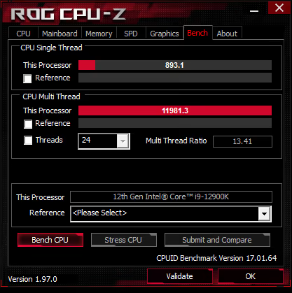
After all done and stable, run somes bench tests…
The MT results must be befitting P-51x / E-40x
The ST results will be temp dependent.
The Aida memory latency test is good check the effective ST clock .


Understanding ASUS OCTVB:
I'll try to make OCTVB easy...
Let's use my actual manual OCTVB settings as an example:

First line is for only 1 active P-core.
So this line will be used when only 1 core (anyone) is active, and the others are parked or not loaded.
In this condition, If Core temp is < 60 this core will run 57x.
If temp is 60 to 69 this core will run 56x.
If temp is >= 70 this core will run 55x
The second line is for when 2 cores (anyone) are active and the others are sleeping or not loaded.
If temp < 56 these 2 cores will run 57x.
If temp is 56 to 65 these 2 cores will run 56x
If temp is >= 66 these 2 core will run 55x
The third line is for when 3 cores (anyone) are active and the others are sleeping or not loaded.
If temp < 52 these 3 cores will run 57x.
If temp is 52 to 61 these 3 cores will run 56x
If temp is >= 62 these 3 core will run 55x
The fourth line is for when 4 cores (anyone) are active and the others are sleeping or not loaded.
If temp < 66 these 4 cores will run 55x.
If temp is 66 to 75 these 4 cores will run 54x
If temp is >= 76 these 4 core will run 53x
So let's go to the last line....
The last line is for when all cores are active and loaded.
If temp < 72 these 8 cores will run 53x.
If temp is 72 to 81 these 8 cores will run 52x
If temp is >= 82 these 4 core will run 51x
Once understood lets try some tricks:
You can use "8 Active Core tempB" = 100C to change the full load logic.

This way your full load will be 52x, because when 8 cores are active and loaded, and temp hit 72 the freq. will drop from 53x to 52x... and the next temp step is the TJmax.
Another trick:
You can chage the BinA (or BinB) to force 2 drops:

So when 8 Active cores are loaded and temp hits 72C, freq. will be 51x, and when they hit 82C, freq. will be 50x.
TempA is linked to BinA and TempB is Linked to BinB
You can change BinA and BinB changing the frequency more than 1 step in any position.
Adding few "º C" to the table:
This table below is an Asus +2Boost profile automatically calculated by the Asus algo for the following "by core" configuration:
58x2 - 57x3 - 55x5 - 53x8.

You can edit all the temps adding a few degrees..
+15C to the 53x8 (6,7,8 active cores)
+ 5C to the 55x5 (4 and 5 active cores)
And keep 57x3 and 58x2 untouched.

And you can try any kind of combination that you can boot... LOLOLOL
I use to test with the Asus OCTool and when I find some nice setting I write to the BIOS.
Below you can see a real example:
This is the Asus +2 Boost Profile

Applied +5ºC to the entire table:

Applied +10ºC to the entire table:
Below we changed the full load frequency from 51x to 52x setting 100C to the "8 Active Core" TempB


Notes:
The use of LLC#1 was purely a personal choice. The procedure is valid for any LLC# that you find most convenient.
The 1500mv "IA VR Voltage limit" limits the Vcore voltage and the maximum frequency of the OCTVB, this value was also a personal choice.
The default LLC is the #3. If you want to keep your hardware overclocked as close to spec as possible, use the LLC#3 set:
LLC#3
DC_LL 1.1
AC_LL 0.25 (if you have a really good CPU, you can try decreasing AC_LL from 0.25 to 0.20. If your CPU is not so good, try 0.30 or 0.35)
Boot the system with the following settings:
LLC=#1
AC_LL=0.60
DC_LL=1.75
C-State = Enable
Voltage Optimization = Enable
IA VR voltage Limit=1500 (or the limit you think is good for you)
By core = P-51x8 / E-40x8
Adaptive voltage (AUTO)
''''''''''''''''''''''''''''''''''''''''''''''''''''''''''''''''''''''''''''''''''''''''''''''''''''''''''''''''''''''''''''''''''''''''''''''''''''''''
It's time to test system stability in Full Load.
Run the CB-R23 and check the stability of the system.
''''''''''''''''''''''''''''''''''''''''''''''''''''''''''''''''''''''''''''''''''''''''''''''''''''''''''''''''''''''''''''''''''''''''''''''''''''''''
If the system is not stable change to the LLC#2 settings:
LLC=#2
AC_LL=0.46
DC_LL=1.46
C-State = Enable
Voltage Optimization = Enable
IA VR voltage Limit=1500 (or the limit you think is good for you)
By core = P-51x8 / E-40x8
Adaptive voltage (AUTO)
''''''''''''''''''''''''''''''''''''''''''''''''''''''''''''''''''''''''''''''''''''''''''''''''''''''''''''''''''''''''''''''''''''''''''''''''''''''''
Continue increasing the settings of the Load Line set until you achieve stability by running the CB-R23.
''''''''''''''''''''''''''''''''''''''''''''''''''''''''''''''''''''''''''''''''''''''''''''''''''''''''''''''''''''''''''''''''''''''''''''''''''''''''
Note: It is very likely that using the LLC#1 settings the system will be stable, with reasonable voltages and temperatures.
If the system is stable running CB-R23, write down the full load values:
Core_VIDs =
Core_Clock_P =
Core_Clock_E =
Core_Temp =
IA_Core_Power =
Vcore =
CPU_Core_Current =
VRM_Vcore_Current =
VRM_Vcore_Power =
''''''''''''''''''''''''''''''''''''''''''''''''''''''''''''''''''''''''''''''''''''''''''''''''''''''''''''''''''''''''''''''''''''''''''''''''''''''''
If the Load Lines configuration was done correctly you will see that vrm power (VRM Vcore Power) and CPU power (IA Core Power) will have very close values at Full Load. The same will happen with VID and VCore.
''''''''''''''''''''''''''''''''''''''''''''''''''''''''''''''''''''''''''''''''''''''''''''''''''''''''''''''''''''''''''''''''''''''''''''''''''''''''
Adjusting the minimum voltage to full load P-51x / E-40x
Now it's time to lower Vcore to the lowest possible level while maintaining system stability, just as we do when using "sync all cores" and "fixed voltage".
To do this you can use Asus OCTool, Asus’s exclusive tool for changing BIOS parameters "on-the-fly".
*To use this tool, disable "Windows Memory Integrity" and/or "Intel VMX" in BIOS.
For those who do not have an ASUS MB the solution is to each change reboot the system to make changes directly to the BIOS.
Offset changes to VF points made with OCTool are not permanent, and on an upcoming system restart the BIOS settings will be reapplied.
The offset values defined with OCTool should therefore be applied again to each reboot.
Note: Some OCTool functions can be critical, so if you don't know what it's for, don't mess with it. 😊
With OCTool you can do the entire VCore adjustment procedure for full load with few system reboots.
Once the value of the offsets that generate the desired VCore has been found, these values should be applied directly to the offsets of the BIOS VF curve.
Regardless of which method you use, the procedure will be the same: use the points of the VF curve to reduce the VID of the full load frequency.
If the VF table has a VF point for the chosen full load frequency, simply reduce the VID of this point until it is no longer possible to run the CB-r23 and/or the system becomes unstable. In this case we should use a VID 5mv or 10mv above the stability limit.
If there is no unique point for full load frequency (as in the case of the 51x frequency of 12900K), you will need to lower the voltage of the table points before and/or after the chosen full load frequency.
In our example of the full load 12900K (P51x), the near control points are VF#6 (4800MHz) and VF#7 (5300MHz). Although the P51x is closer to the VF#7 (53x), a negative offset at this point is not a good option to reduce the full load voltage of the 51x frequency, as the voltage reduction of this point will influence the interpolation voltage of frequencies greater than 5300MHz. Thus, we must use the VF#6 to reduce the full load voltage of 5100MHz.
Let's start by making a reduction of 10mv at 10mv at the VF#6 point until it reaches a point where the CB-r23 becomes unstable. After finding the point of instability, just increase the offset of VF#6 by 10mv, test again, and if the system is stable, we can write this VF#6 offset directly into the BIOS.
Since the frequency and full load voltage are already set, it is time to set the other impulse frequencies.
About E-cores
There is no VF curve for the E-cores. So how can I know the minimum voltage for each e-core frequency?
First, you need to sync all e-cores to 40x.
In Windows, select the power plan "Power Saver" and run r23. Write down the VID of the e-cores.
If you want to know the voltage for 41x, 42x, etc, synchronize all e-cores and repeat the test.
The full load VID of the P-cores must be sufficient for the E-cores, otherwise the system will crash.
Defining the By Core Usage:
You can define multiple core groups to assign to them a specific frequency, or just define the frequency groups and let the CPU itself define which cores will operate within a group and at what time.
Examples of configurations for performance cores:
P: 58x1 - 57x2 - 56x3 - 55x4 - 54x5 - 53x6 - 52x7 - 51x8 (Eight frequency groups)
P: 58x1 - 57x3 - 55x5 - 53x7 - 51x8 (Five frequency groups)
P: 57x3 - 55x5 - 53x6 - 51x8 (four frequency groups)
P: 55x3 - 53x5 - 51x8 (Three frequency groups)
As we set the full load frequency to 5100MHz, any configuration adopted must respect the value of 51x for the maximum number of cores (51x8).
Whatever the configuration chosen, number of groups or maximum frequency, so that the full load on P51x is respected we must assign the 51x to the 8 cores.
The same concept applies to efficiency cores.
We will adopt the following configuration as a starting point:
LLC=#1
AC_LL=0.60
DC_LL=1.75
(or the load line set of your choice to achieve full load Vcore for P-51x/E-40x)
C-State = Enable
Voltage Optimization = Enable
IA VR voltage Limit=1500mv (or the limit you think is good for you)
VF#6 = Negative offset (the one you have already found for Full Load)
VF#7 = positive offset 40mv (this is a suggestion that will help you run high OCTVB frequencies)
VF#11 = positive offset (1.46 - VID of point #11) ***
Adaptive voltage = 1.46v
By core usage
P: 55x3 – 53x5 – 51x8
E: 42x2 – 41x4 – 40x8
*** Note: Keeping the value of the sum of (VID_VF#11+offset) close to the adaptive voltage value helps in system stability.
When you feel comfortable you can use asus OCTool to set values "on-the fly".
System stability test.
We know that for full load frequencies the system is stable, it remains to be known if it is stable for light loads.
The best stability test for high frequencies is the use of the computer for basic tasks like surfing the internet, YouTube, etc...
The Aida memory latency test is a good way to check the effective clock of the core0.
The CB-r23 ST is also a good way to verify that the system is responding at frequencies greater than P-51x in ST.
The RealBench is good to test the "idle to full load to idle" stability.
ASUS OCTVB:
Once the system is stable it is time to enable Asus TVB profile.
By maintaining the previous settings, simply enable "TVB overclocking� = +1Boost Profile.
*TVB Boost is applied to P-cores only.
In this way, we will have the system operating as follows:
Frequencies:
P: 56x3 – 54x5 – 52x8
E: 42x2 – 41x4 – 40x8
Full Load:p-51x/E-40x
Note that when the 8 P-cores are loaded the frequency is now 52x, however several temperature rules are applied so that in full load the CPU keeps the 8 P-cores at 51x due to temperature.
Any system instability from now on will be due to the high frequencies, never due to the full load frequency (assuming you have correctly set the full load voltage previously)
If you encounter instability at light loads, the following actions can help you return to stability:
Rise Adaptive Voltage;
Rise VF#7;
Rise VF#11;
Rise IA VR Voltage Limit;
Lower max “by core� freq and/or Boost.
If you encounter instability at heavy loads, the following actions can help you return to stability:
Rise AC_LL;
Rise VF#6;
Change the LLC set.
If you have temperature problems, try to lower the full load frequency.
You can try full load at P-50x / E-49x, or any other combination.
Remember to find minimum Vcore for the new frequency chosen.
If your system is stable, it's time to go to the Asus “+2Boost profile� and test whether your system will be able to run in the following configuration:
P: 57x3 – 55x5 – 53x8
E: 42x2 – 41x4 – 40x8
Full Load: P-51x/E-40x
After all done and stable, run somes bench tests…
The MT results must be befitting P-51x / E-40x
The ST results will be temp dependent.
The Aida memory latency test is good check the effective ST clock .
Understanding ASUS OCTVB:
I'll try to make OCTVB easy...
Let's use my actual manual OCTVB settings as an example:
First line is for only 1 active P-core.
So this line will be used when only 1 core (anyone) is active, and the others are parked or not loaded.
In this condition, If Core temp is < 60 this core will run 57x.
If temp is 60 to 69 this core will run 56x.
If temp is >= 70 this core will run 55x
The second line is for when 2 cores (anyone) are active and the others are sleeping or not loaded.
If temp < 56 these 2 cores will run 57x.
If temp is 56 to 65 these 2 cores will run 56x
If temp is >= 66 these 2 core will run 55x
The third line is for when 3 cores (anyone) are active and the others are sleeping or not loaded.
If temp < 52 these 3 cores will run 57x.
If temp is 52 to 61 these 3 cores will run 56x
If temp is >= 62 these 3 core will run 55x
The fourth line is for when 4 cores (anyone) are active and the others are sleeping or not loaded.
If temp < 66 these 4 cores will run 55x.
If temp is 66 to 75 these 4 cores will run 54x
If temp is >= 76 these 4 core will run 53x
So let's go to the last line....
The last line is for when all cores are active and loaded.
If temp < 72 these 8 cores will run 53x.
If temp is 72 to 81 these 8 cores will run 52x
If temp is >= 82 these 4 core will run 51x
Once understood lets try some tricks:
You can use "8 Active Core tempB" = 100C to change the full load logic.
This way your full load will be 52x, because when 8 cores are active and loaded, and temp hit 72 the freq. will drop from 53x to 52x... and the next temp step is the TJmax.
Another trick:
You can chage the BinA (or BinB) to force 2 drops:
So when 8 Active cores are loaded and temp hits 72C, freq. will be 51x, and when they hit 82C, freq. will be 50x.
TempA is linked to BinA and TempB is Linked to BinB
You can change BinA and BinB changing the frequency more than 1 step in any position.
Adding few "º C" to the table:
This table below is an Asus +2Boost profile automatically calculated by the Asus algo for the following "by core" configuration:
58x2 - 57x3 - 55x5 - 53x8.
You can edit all the temps adding a few degrees..
+15C to the 53x8 (6,7,8 active cores)
+ 5C to the 55x5 (4 and 5 active cores)
And keep 57x3 and 58x2 untouched.
And you can try any kind of combination that you can boot... LOLOLOL
I use to test with the Asus OCTool and when I find some nice setting I write to the BIOS.
Below you can see a real example:
This is the Asus +2 Boost Profile
Applied +5ºC to the entire table:
Applied +10ºC to the entire table:
Below we changed the full load frequency from 51x to 52x setting 100C to the "8 Active Core" TempB
Notes:
The use of LLC#1 was purely a personal choice. The procedure is valid for any LLC# that you find most convenient.
The 1500mv "IA VR Voltage limit" limits the Vcore voltage and the maximum frequency of the OCTVB, this value was also a personal choice.
The default LLC is the #3. If you want to keep your hardware overclocked as close to spec as possible, use the LLC#3 set:
LLC#3
DC_LL 1.1
AC_LL 0.25 (if you have a really good CPU, you can try decreasing AC_LL from 0.25 to 0.20. If your CPU is not so good, try 0.30 or 0.35)
Options
- Mark as New
- Bookmark
- Subscribe
- Mute
- Subscribe to RSS Feed
- Permalink
01-18-2022 12:27 AM
Reserved1
Options
- Mark as New
- Bookmark
- Subscribe
- Mute
- Subscribe to RSS Feed
- Permalink
01-18-2022 12:27 AM
Reserved2
Options
- Mark as New
- Bookmark
- Subscribe
- Mute
- Subscribe to RSS Feed
- Permalink
10-06-2022 02:29 PM
First of all, nice guide. Definitely learning about the platform. However, i cannot achieve even a moderate 52x frequency in a very strange way. I have pretty much wasted 2 weeks on this without any success on my 12900k and z690 Hero board.*
*So, with manual voltage i can achieve 53x all core stable. I decided to go with 52x all core though since the cypress increase and thermal imprint would go unreasonably high for very few performance improvements.
I can achieve stability on llc1 but also went for llc2 as it seemed more reasonable.
As soon as I turn on tab and the whole setup, it will boot once, i can then run benchmarks and r23 all night long and it WILL stay at 52x all core frequency.
After a reboot or 2 though, my system with exact same settings will not go above 51x all core though.
For me this is immensely strange. If someone might know the culprit, please tell me as I’m going nuts over this after spending 700€ on a motherboard and the same on a cpu that seems pretty much trash.
*
Options
- Mark as New
- Bookmark
- Subscribe
- Mute
- Subscribe to RSS Feed
- Permalink
10-20-2023 05:48 PM - edited 10-20-2023 05:48 PM
You can find an updated material here
https://www.overclock.net/threads/asus-maximus-z790-and-intel-i9-13900k-14900k-an-overclocking-and-t...
Related Content
- I9 13900k undervolting adventure in Intel 700 & 600 Series
- Maximus XIII Hero LLC impedances? in Intel 500 & 400 Series
- Asus TUF Z690 D4 and 13700k watt consumption problem in Intel 700 & 600 Series
- Strix z790-a D4+ i9 13900k-"Ghost in PC" in Intel 700 & 600 Series
- ASUS Trained SVID Behaviour in Intel 700 & 600 Series
